General
Anatomy
- The C1 lateral mass screw is partially threaded to reduce irritation of the C2 nerve root and subsequent neuropathic pain.
- The atlas consists of two thick lateral masses situated at the anteromedial part of the ring, which are connected in front by a short anterior arch and posteriorly by a longer curved posterior arch.
- The superior articular facet is an oval, concave facet that faces upward and medially to articulate with the occipital condyle.
- The inferior articular facet is a circular, flat, or slightly concave facet that faces downward, medially, and slightly backward and articulates with the superior articular facet of the axis.
- The medial aspect of each lateral mass has a small tubercle for the attachment of the transverse ligament of the atlas.
- The transverse process projects from the lateral masses.
- The upper surface of the posterior arch adjacent to the lateral masses has paired grooves in which the vertebral arteries course.
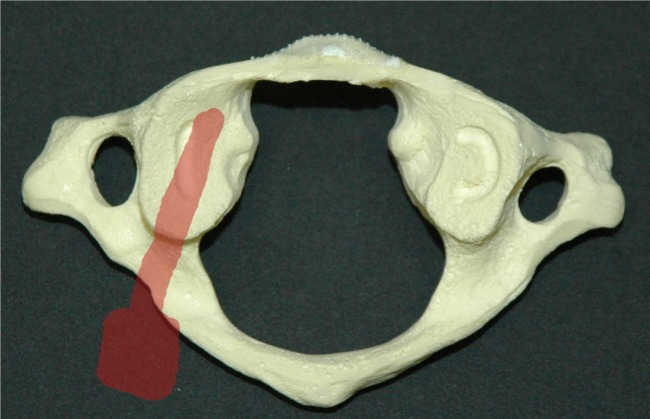
A, superior view;
- Inferior view
- Anterior view
- Posterior view
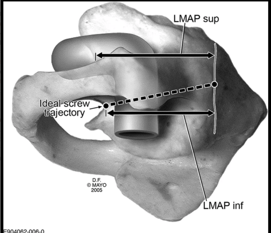
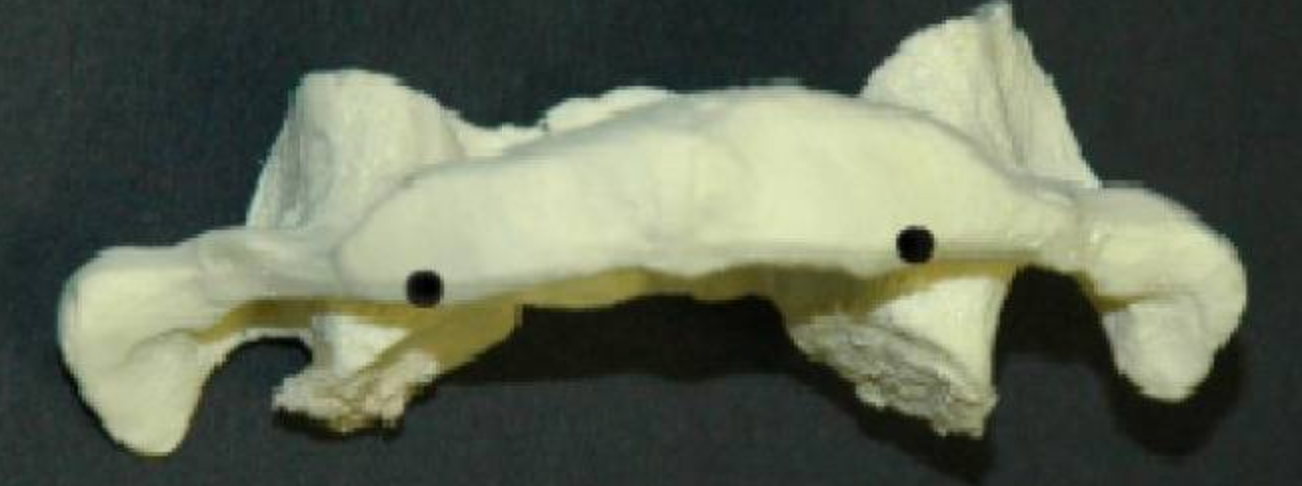
- Lateral view of C1 demonstrating the ideal orientation of screw placement within the sagittal plane (10°–15° caudad to cephalad).
- Note the starting position below the posterior ring confluence with the lateral mass.
- The arrows represent the following dimensions:
- LMAPsup, lateral mass anteroposterior dimension superior to the posterior ring insertion;
- LMAPinf, lateral mass anteroposterior dimension inferior to the posterior ring insertion.
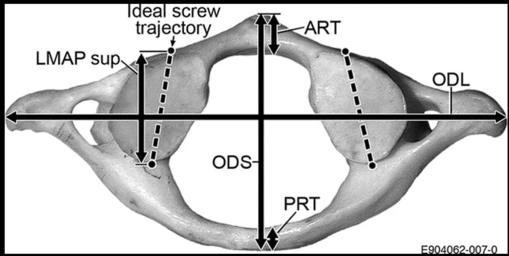
- Superior view of C1 demonstrating the ideal orientation of the screws within the transverse plane (5°–10° medially directed from the sagittal plane), in addition to various other measured dimensions:
- LMAPsup, lateral mass anteroposterior dimension superior to the posterior ring insertion;
- LMAPinf, lateral mass anteroposterior dimension inferior to the posterior ring insertion;
- ODS, outer diameter of the vertebra in sagittal orientation;
- ODL, outer diameter of the vertebra in coronal/lateral orientation;
- ART, anterior ring thickness (in anteroposterior dimension);
- PRT, posterior ring thickness.
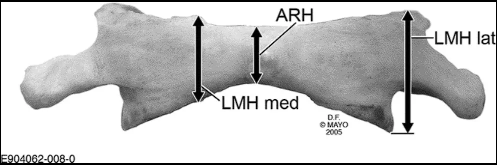
- Anterior view of C1 showing the measurement of anterior height (ARH), as well as the height dimensions of the lateral mass (LMHmed and LMHlat).
- The choice of technique depends on the
- C1 vertebra anatomy
- Height and width of the arch, pedicles, depth of the VA sulcus, the size of the lateral masses, and the presence of anomalies
- Vessels anatomy
- V3 segment
- Posterior inferior cerebellar artery
- C1–C2 venous plexus
Lateral Mass screw/sublaminar LMS C1 screw
- Prep
- C1 lateral mass is dissected out by first performing bipolar electrocautery and taking down the atlantoaxial membrane.
- A Penfield dissector is then placed inferior to the posterior arch of C1, down onto the C1 lateral mass, and is swept inferiorly, which allows for the mobilization of the C2 nerve root.
- During this portion of the procedure, bleeding is controlled with a combination of hemostatic agents, including
- Thrombin-soaked Gelfoam
- Surgicel
- SURGIFOAM powder
- Cottonoids
- Once all the anatomic landmarks are dissected out, the C2 nerve root is retracted caudally.
- Entry point
- Working window is bordered
- Cephalad by the posterior arch of C1
- Caudad by the C1 to C2 joint
- Medial-lateral by the bony limits of the lateral mass, which can be palpated with a small periosteal elevator.
- Rajashekaran:
- Just lateral to the medial border of the C1 lateral Mass
- The posterior arch of C1 might overhang the lateral mass.
- How to deal with it
- The trajectory of the screw can be safely and appropriately repositioned to traverse the posteroinferior arch before entering the lateral mass OR
- Inferior portion of the C1 arch can be resected to enlarge the window to improve visualization of the lateral mass of C1.
- The starting point is marked with either a 2-mm cutting burr or an awl.
- Trajectory
- Hold the medial part of the C1 lateral mass to help medio lateral trajectory
- The C1 lateral mass is then drilled with a power drill under lateral view fluoroscopy to confirm the appropriate sagittal trajectory.
- Approximately 10 degrees medial and 22 degrees cephalad.
- Directed towards the anterior arch of C1
- Rishi
- Make sure the screw is just posterior to the tip of the anterior arch. Too anterior can touch the carotid artery
- Drill the cortex first and then use the tap to drill the rest of the direction.
- Should get bicortical purchase
- Anterior drilling is completed when the tip of the drill bit reaches the anterior cortex of the dens at the level of the midportion of the anterior tubercle of C1, On lateral view fluoroscopy.
- After palpation of the drill path with a ball-tip feeler, the pilot hole is then tapped and a 3.5-mm screw, typically 26 to 32 mm in length, is inserted
- Screw length is preoperatively estimated by using CT.
- Use bone graft at the end
- Cons
- Profuse bleeding from venous plexus
- C2 root damage.
- Retracting the C2 nerve root
- C2 nerve root is retracted caudally to expose the C1 lateral mass.
- Entry point
- Middle of the junction of the C1 posterior arch and the midpoint of the posterior inferior part of the C1 lateral mass.
- Trajectory
- The medial wall of the C1 lateral mass can be readily palpated with a Penfield dissector, which serves as the medial border of the screw trajectory.
- 3 mm drill bit with drill guide are used to drill a pilot hole
- AP C arm: 5° to 10° of medial angulation to penetrate the anterior cortex of C1.
- Lateral C arm, the drill is aimed towards and slightly caudal to the anterior tubercle of C1 in the cranial-caudal direction;
- this will avoid possible violation of the atlantooccipital joint if the drill is aimed too cranially
- The hole is then tapped, and the C1 lateral mass screw is placed after measuring the screw length with a feeler probe (usually 34 to 36 mm).
- a 3.5 mm polyaxial screw of an appropriate length is inserted into the lateral mass of C1 to achieve bicortical bony purchase
- Pros
- Keep C2 nerve root
- Cons
- persistent postoperative pain associated with irradiation along the root.
- Cutting the C2 root to prevent this complication
- C2 nerve root is sacrificed proximal to the C2 ganglion to facilitate the exposure of the C1–2 facet joint
- Entry point
- Medial-lateral:
- At the center of the C1 lateral mass
- Cranial-caudal
- Slightly inferior to the junction of the posterior arch and the inferior lateral mass
- Trajectory
- The medial wall of the C1 lateral mass can be readily palpated with a Penfield dissector, which serves as the medial border of the screw trajectory.
- 3 mm drill bit with drill guide are used to drill a pilot hole
- AP C arm: 5° to 10° of medial angulation to penetrate the anterior cortex of C1.
- Lateral C arm, the drill is aimed towards and slightly caudal to the anterior tubercle of C1 in the cranial-caudal direction;
- this will avoid possible violation of the atlantooccipital joint if the drill is aimed too cranially
- The hole is then tapped, and the C1 lateral mass screw is placed after measuring the screw length with a feeler probe (usually 34 to 36 mm).
- Note
- Vertebral artery often runs in the sulcus arteriosus on the superior-lateral aspect of the C1 posterior arch, thus care must be taken to avoid inadvertent injuring to the vertebral artery during drilling in this area.
- A bony bridge, the arcuate foramen (ponticulus posticus) may overlie the vertebral artery due to calcification of the oblique atlanto-occipital ligaments and may be mistaken for the C1 lateral mass.
- Pros
- Can reduce bleeding
- Shorten the operation time.
- Cons
- Risk of chronic occipitalgia remains;
- Persistent numbness in the occipital region is formed in a greater number of cases.
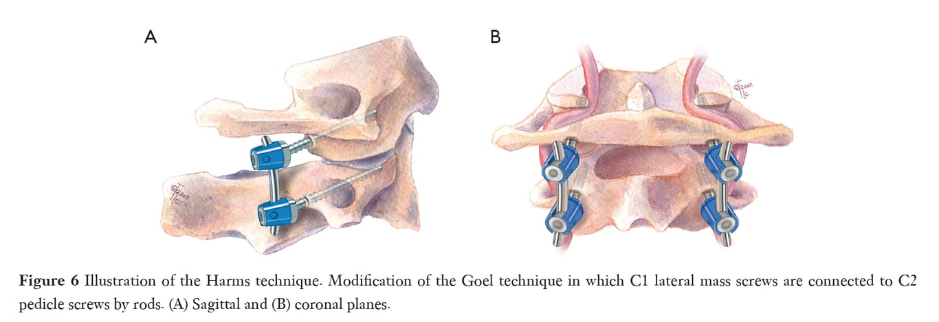
Harms technique
Goel technique
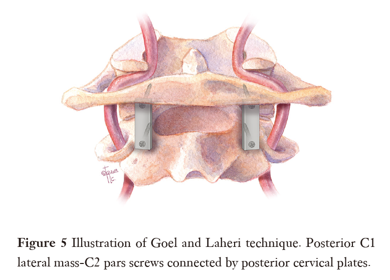
Posterior arch screw/C1 pedicle screw
- C1 pedicle screw
- C1 pedicle screws are considered the most mechanically correct method since it is allowed to implant a longer screw.
- This option is useful in deformity surgery or in patients with severe osteoporosis in whom purchase of LMS may be questionable.
- The main problem for use C1 pedicle screw is the risk of VA injury due to the narrow pedicle or arch and deep VA groove.
- The reported incidence of the VA injury with C1–C2 screw fixation ranges from 1.7% to 5% in the reported literature.
- Narrow C1 lamina/pedicle can lead to VA injury (if the VA is not visualized and mobilized and the screw is inserted “blindly”).
- In various populations of adults
- 19.2% to 53.8% had narrow C1 pedicle (<4 mm),
- The thickness of the C1 arch/lamina in the area of pedicle screw implantation <4 mm is a risk factor for VA injury.
- 49% had internal pedicle diameter <1 mm,
- 38% had no intramedullary canal.
- The average C1 pedicle thickness in women lesser than in men.
- Performed in
- adult patients and even in some of paediatric patients > 7 years
- contraindicated in patients < age 6 years
- Technique (Menger 2015)
- Entry point
- Coronal view:
- Trajectory
- The screw is placed directly superior to the mid-point of the C2 lateral mass.
- The cranial-caudal direction is then obtained on lateral fluoroscopy with stopping point noted to be just behind the anterior tubercle of C1.
- The standard 10-degree medialization is maintained in screw trajectory.
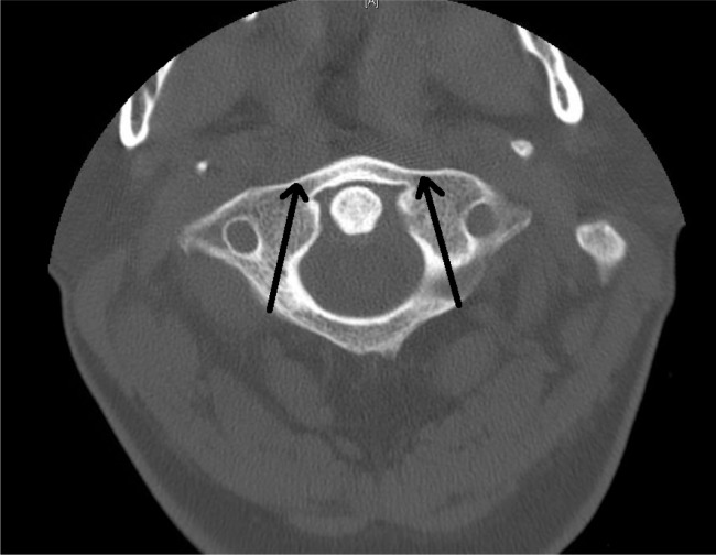
Axial view
- Pros
- reduces the possibility of injury to the paravertebral venous plexus and C2 nerve root
Supralaminar C1 LMS
- Fully supralaminar C1 LMS are suitable for use in V3 segment anomaly when the vessel above the C1 pedicle is absent, in this case, there is no need for dissection and mobilization of the artery above the arch
- Technique
- GA in the prone position, head fixed in a Mayfield head clamp.
- Standard midline incision and subperiosteal dissection of paraspinal muscles was made to expose the occiput, posterior C1 arch, and C2 lamina.
- The occiput and C1 arch were dissected approximately 20 mm lateral to the midline. The VA was identified coursing along its groove and it was dissected cranially away from the groove (using microscope or loupe).
- The loop was retracted superiorly until the posterior surface of C1 LM is rendered.
- Two penfield dissectors are placed above and under the edges of the C1 arch approximately in the middle in the area of the entrance to the C1 lateral mass for VA (above) and venous plexus (under) protection.
- An entry point on the upper edge of the posterior arch of the atlas, 4 mm laterally to the medial surface of the lateral mass, is then chosen.
- The lateral mass was then perforated using a hand-held drill under X-ray control, a probe was used to explore the walls of the hole.
- The trajectory was approximately 0°–5° in the medial direction and 0° in the cephalad direction.
- The optimal direction of the trajectory was individual, depending on the preoperative measurements and intraoperative anatomy.
- The hole was tapped and a 3.5 mm screw was inserted (screw length: 26–30 mm).
- The screws were inserted taking care to leave enough space between the screw head and the occipital squama for the VA.
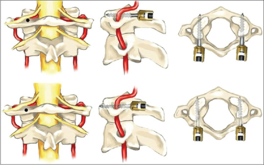
- Schematic representation of C1 lateral mass screwing techniques over the arch (upper row) and partially over the arch (bottom row)
- We recommend using partially threaded screws in such cases. If the screw is fully threaded, it is necessary to lay a non-absorbable gasket between the screw and the VA (autofascia for example).
 Made with Bullet