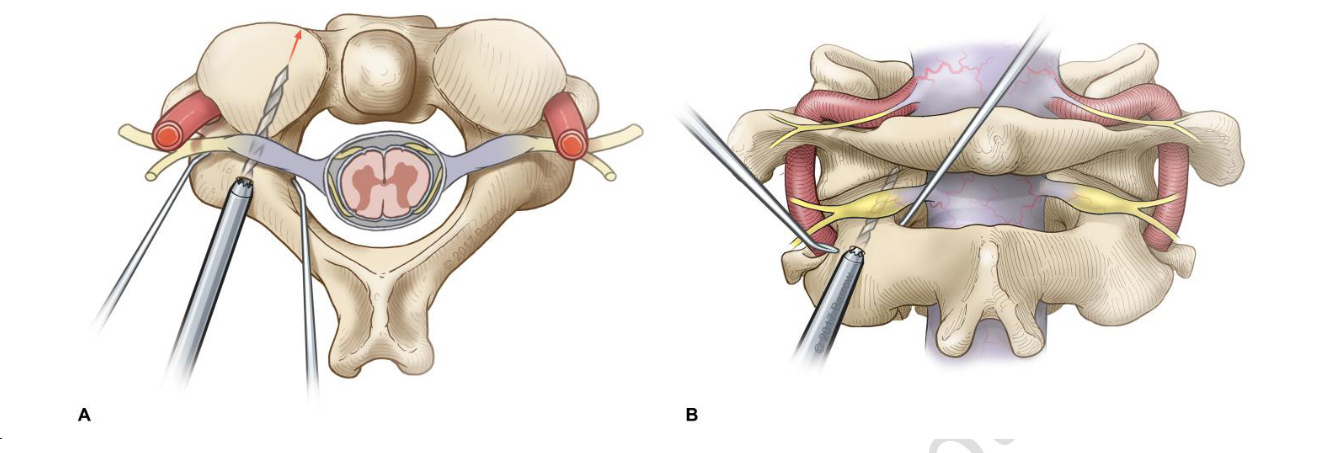
C2 dissection
- When dissecting the C2 one can use the C2 pars and slide down into the C1/2 joint space.
- Cut the C2 nerve root distal to the DRG if possible.
- The vertebral artery is more lateral than the C1/2 joint so do not worry about damaging it when trying to enter the C1/2 joint
- The C1 lateral mass/ C1/2 joint is lateral to the theca.
C2 fixation techniques
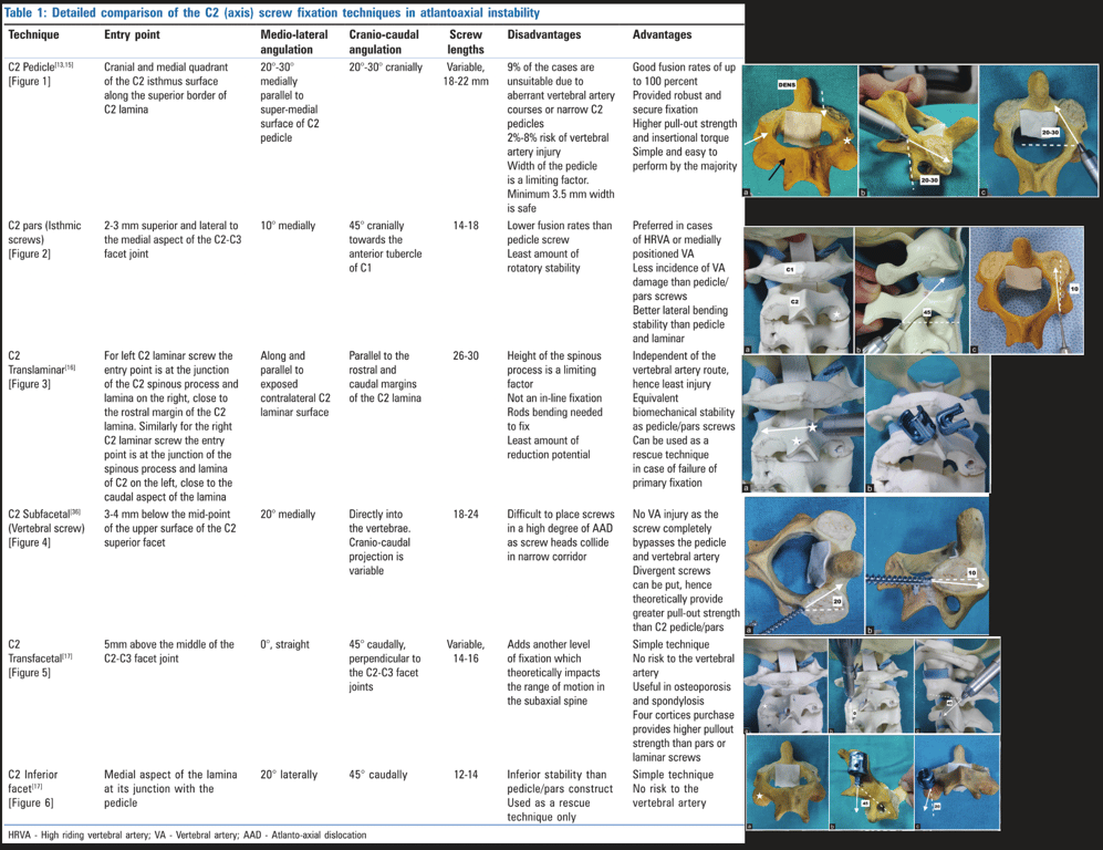
C2 Pedicle screw
Freehand screw placement
- Entry point
- AS:
- Look at the angle of the medial border of pedicle draw a line following this angle proximally and translate this line slightly laterally. This will be the entry point.
- RMK: starts just lateral to the border of the lamina.
- The more caudal the starting point, the harder it is to get into the pedicle and the easier it is to hit the artery.
- A pilot hole was then made with a high-speed drill.
- The entry point for pedicle screw placement was in the medial and superior quadrant of the pars surface.
- A 2.5-mm twist drill was then advanced to the desired depth with periodic interrogation of the drill path with a ball-tip probe.
- After exposure of the C2 lamina and lateral mass, the C2 pars and pedicle were bluntly dissected in a subperiosteal fashion.
- An assistant placed a Penfield 4 dissector along the medial border of the pedicle to aid with visualisation and trajectory.
- Drill through the full depth of the C2 pedicle and let the screw do the rest.
- If a significant increase in resistance was encountered with the drill before reaching the desired depth, the cannulation was halted at that depth. After tapping, an appropriately sized screw was placed along the same path
2. Pars screw
3. Transarticular screw
2. Pedicle screw
- Joaquim 2020
Technique | Entry point | Lateral angulation | Sagittal angulation |
Abumi et al. | Starting slightly lateral to the center of the lateral mass and close to the inferior margin of the lower facet joint of the cranially adjacent vertebra | About 25° to 45° medially oriented | Parallel to the superior endplates for C5, C6 and C7 pedicles; slightly cephalad oriented for the C2, C3 and C4 pedicles |
Navigated screw placement
- A reference frame was attached either to the Mayfield clamp before sterile draping or to a spinous process after the exposure was complete.
- The cervical CT images were obtained with the O-arm
- The images were then transferred to the StealthStation surgical guidance system (Medtronic, plc), and instruments were registered and verified for accuracy.
- The entry point for pars and pedicle screws was determined by the CT image guidance with the goal of optimizing screw length and avoiding neurovascular structures.
- A navigated drill guide and power drill were advanced down the desired trajectory while using the image guidance system. The ball-tip probe was then used to interrogate for any breaches. After tapping, the screw was placed down the same trajectory.
- Danger
- Up to 20% of patients do not have pedicles of a sufficient size to receive a screw – in such cases, consider a pars screw, a laminar screw or wiring/hook technique.
- CT
- Check the size of the pars of the axis:
- Using a parasagittal CT scan reconstruction check that there is atleast 3mm thickness to the pars (can scroll 3x on a 1mm cut CT medio-laterally)
- Identify if there is an anomalous medially located vertebral artery. If there is cannot perform transarticular screw
Complications
- Similar between the groups: 3 vertebral artery injuries (2 [1%] freehand, 1 [2%] navigated; P>0.99)
- 2% stroke in the navigated group
- No breaches (grade A) occurred in 113 (86%) of the freehand screws and in 34 (67%) of the navigated screws
- More screws had acceptable placement in the freehand group (123/131, 94%) than in the navigated group (42/51, 82%) (P=0.02)
- High riding vertebral artery - Klepinowski 2021
- Aka medially placed vertebral artery
- A high-riding vertebral artery (HRVA) has been defined as a C2 isthmus height (C2IsH) of ≤ 5 mm and/or C2 internal height (C2InH) of ≤ 2 mm at the level 3 mm lateral to the border of the spinal canal
- C2 isthmus height** <5mm
C2 Pars screw
Positioning
- A gauze roll is placed in the patient mouth after intubation to allow anteroposterior fluoroscopy if transarticular screws placement is planned
- mandatory to perform a meticulous subperiosteal dissection and exposure of the posterior arch of C1 and also the spinous process, lateral masses
and lamina of the axis. The C2–3 joint is minimally exposed
Entry point
- Craniocaudal: Go as close to the C2/3 joint (3-5mm cranial to the joint) but not violating it and stay in line with the other lateral mass screw.
- Medio-lateral: Start as medial as possible but without violating the spinal canal and the medial portion of the pars
- Trajectory
- Sagittal plane:
- Angle to parallel to the C2 Pars i.e. go as angle as your can without cutting through the C2 Pars
- A hand drill is made parallel to the pars interarticularis in a lateral fluoroscopy (generally, great craniocaudal inclination is required for maintaining a parallel trajectory to the pars).
- It is important to evaluate the foramen transversum: most of the times, they are just anterior to the posterior vertebral line
- The trajectory was aimed toward the junction of the pars and superior facet under direct anatomical visualisation
- Axial:
- Go straight or at most angle slightly medially.
- Difference vs pedicle screw:
- The entry point was typically more inferior and lateral than that used with a pedicle screw, approximately 4 mm lateral and cranial to the inferomedial border of the C2-3 facet joint.

2. Pars screw
3. Transarticular screw
2. Pedicle screw
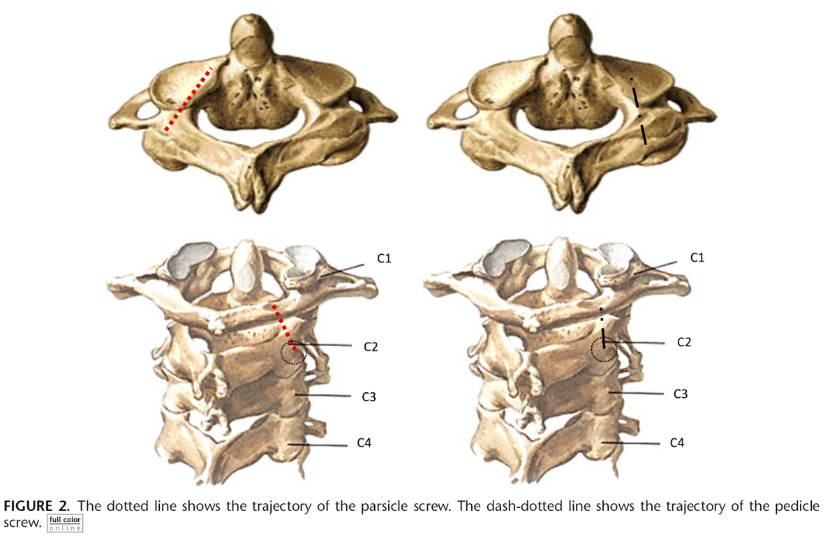
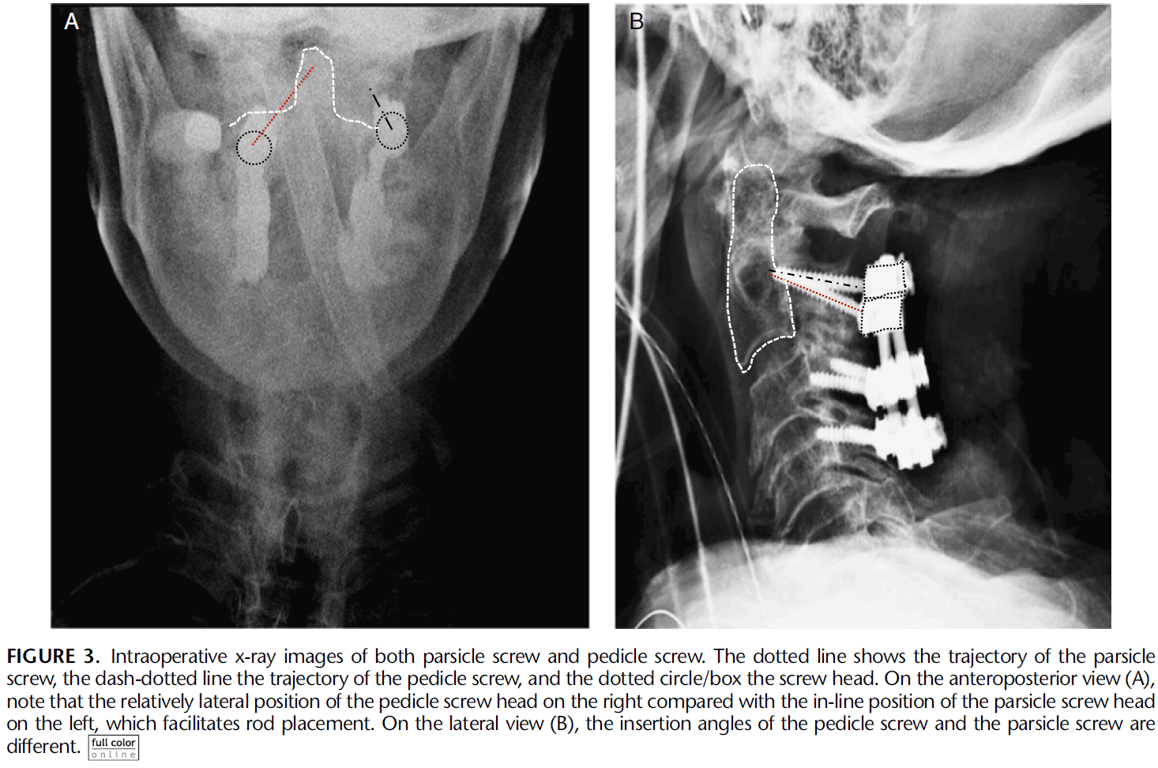
C2 Parsicle screw
- Entry point:
- Cranial to the C2–C3 facet joint, in a position inferior and medial to that of the starting point of a traditional C2 pedicle screw.
- Angulation
- Medial inclination: 15–20 degrees,
- Cranial-caudal angulation : 30 and 45 degrees
- Depending on the slope of the lateral mass
- Penfield 4 along the medial border of the pedicle and direct the tap in the dorsolateral aspect of the pedicle to maintain maximum distance from the VA and engage the dorsal cortex of the pedicle.
- Direct as cephalad as possible without violating the dorsal cortex of C2
C2 Transfacetal screw
- Between C2 and C3
- Technique
Technique | Entry point | Lateral angulation | Sagittal angulation |
Takayasu et al. | In an imaginary point on the vertical line bisecting the lateral mass (midway inferior third of the lateral mass) | Straight, no lateral angulation | 60° to 80° caudally |
DalCanto et al. | 2 mm caudal to the midpoint of the lateral mass | 20° laterally | 40° caudally |
Klekamp et al. | 1 mm medial and 1 to 2 mm caudal to the midpoint of the lateral mass | 20° laterally | 40° caudally |
Miyanji et al. | Midpoint of the lateral mass | Neutral to 5° laterally | Perpendicular to the joint in the cephalocaudal direction |
C2 Transarticular Screw
- Between C1/2
Pre-op check
- CT
- Check the size of the pars of the axis:
- Using a parasagittal CT scan reconstruction check that there is atleast 3mm thickness to the pars (can scroll 3x on a 1mm cut CT medio-laterally)
- Identify if there is an anomalous medially located vertebral artery. If there is cannot perform transarticular screw
- Intraop xray:
- Total reduction of the C1–2 joint is necessary for transarticular screw placement.
- Preoperative traction may be used for reduction. In cases where total reduction is not possible, lateral mass screw fixation of the atlas should be performed, with another isolated C2 screw fixation technique (pedicle, pars or lamina screws).
- One can also reduce the joint intraoperatively using cables under C1 and around C2.
Positioning
- A gauze roll is placed in the patient mouth after intubation to allow anteroposterior fluoroscopy if transarticular screws placement is planned
- mandatory to perform a meticulous subperiosteal dissection and exposure of the posterior arch of C1 and also the spinous process, lateral masses
and lamina of the axis. The C2–3 joint is minimally exposed
Exposure
- The medial and superior edges of the C2 pedicle are palpated to avoid breaking the cortical bone.
- Removal of the C1–2 articular cartilage is recommended to improve fusion rates, especially if iliac crest autograft is not utilized.
- A threaded guide pin is preferentially used, estimating the skin entry point lateral to the neck with lateral fluoroscopy in the trajectory of the screw throughout the pars and into the lateral mass of C1.
- If necessary, an auxiliary lateral stab incision is performed, at approximately the T2–4 area.
- Therefore, the skin must be prepped out to the mid-thoracic spine.
- This additional incision minimizes the length of the main midline skin incision, especially when only atlantoaxial fusion is planned (not including the subaxial cervical spine).
- The screwdriver should be passed percutaneous and then the screw must be locked to the screwdriver near the screw entry point, to avoid losing it in the paraspinous muscles.
Entry point
- Craniocaudal: Go as close to the C2/3 joint (3-5mm cranial to the joint) but not violating it and stay in line with the other lateral mass screw.
- Medio-lateral: Start as medial as possible but without violating the spinal canal and the medial portion of the pars
Trajectory
- The trajectory of the pin guide is directed toward the center of the atlas lateral mass (on anteroposterior view) and toward the anterior arch (on lateral view).
Screw insertion
- The pins are then measured for proper screw length selection.
- When inserting a cannulated screw, it is necessary to make sure that there is a good C1-2 alignment, without any distraction at the C1–2 joints (axial support in the vertex of the head may be performed by the auxiliary surgeon to avoid joint distraction).
- Also, frequent fluoroscopic images should be obtained to make sure that the guide wire is not advanced during the drilling and screwing, as one can inadvertently advance it into the cranium.
- After bilateral screw insertion, the lamina of the axis and the posterior arch of the atlas are decorticated for receiving bone graft.
- A supplemented wiring technique in the posterior arch of C1 and the lamina of C2 may be performed to improve fusion rates at surgeon’s discretion
- Borders of the screws
- excessive cranial angulation may result in violation of the condyle-C1 joint;
- an inferior trajectory may result in inadequate fixation of the C1 lateral mass;
- Too medial trajectory results in injury to the spinal cord
- Too lateral trajectory results in additional risk of vertebral artery injury
- if one vertebral artery is injured, the surgeon should not insert a contra lateral screw, since bilateral vertebral injury may result in death or catastrophic stroke
- Average screw length 20-30mm
2. Pars screw
3. Transarticular screw
Lamina screws
- Preop
- CT: Measure length of lamina
- Exposure:
- Subperiosteal dissection exposure of the posterior arch of C1, of the spinous process, the lateral masses and the lamina of the axis.
- Entry points:
- The junction of the lamina and the spinous process.
- On one side, a small cortical hole is performed with high speed drill in the upper portion of the spinous process-lamina junction.
- For example, an upper hole in the spinous process-lamina junction of the right side is made for a left laminar screw.
- A hand drill is used to guide the trajectory of the screw (based on length measure on CT)
- Trajectory
- Aligned with long axis of the contra lateral lamina directed to the laminar surface, but not too much to avoid cortical breakthrough into the spinal canal.
- If the dorsal lamina is perforated, there is no problem. In fact, in osteoporotic individuals, perforation of the dorsal cortex insures a bicortical screw with a stronger purchase than a purely intra-laminar screw.
- A Penfield dissector may help to palpate the inner portion of the lamina that may help directing the hand drill prior to screw insertion.
- A small ball probe is then used to make sure that there was no spinal canal violation.
- On the other side, another hole is performed in the spinous process-lamina junction, but in its inferior portion, in order to avoid crossing both screws at the midline.
- The same trajectory is made on the other side, directing the long axis of the lamina with a hand drill, followed by a ball probe to palpate the bone trajectory and then screw insertion.
- Screw insertion
- The screw inserted is generally 3.5 to 4 mm.
 Made with Bullet